Saturday, November 28, 2015

November 28 Update - More cockpit and OX-5

I hope everyone had a nice Thanksgiving and have awakened from your turkey coma!

Small bits of progress were made the past couple of weeks.  First, the cockpit area:

Front seat

Side panels
 I got the front strips welded on that hold the upper sheet metal over the front cockpit.  Shown on the top longeron to the left of the photo.

I had to make the aluminum pieces that are also on the top longerons.  These will go on last, after the fuselage is covered.  The leatherette material on the inside will tuck under these.  The upper fuselage sheet metal will cover the outside and hold them in place.
Inside of rear cockpit opening sheet metal


Here the interior sheet metal is finally fitted up and temporarily installed.  Andy had these parts made back in the '60's when he first bought the project.  They were made by a United Airlines mechanic - back when the airlines had craftsmen and not just parts changers.  Andy was a UA captain until his retirement in the mid '80's.  Andy didn't get much farther on the restoration.  The airplane sat in his shed until I acquired it in 2011.


These are some pictures of the crudely painted original pieces. I'm happy to have these as they will allow for good paint matching.


Original brushed-on color

Original side panels


Again, with beautiful brushed finish!
On the OX-5, I wanted to have the cylinders on by this next post, but realized I had to finish up a few things first.  I didn't leak-check the cylinders after installing the valves.  I like to do it with stoddard solvent.  Just invert the cylinder, pour in about a cup, let it sit for a few minutes and check for leaks around the valves.  I had to touch up a few with lapping compound, but otherwise they came out fine.

Cylinder base gaskets

Picked up some new cylinder base gaskets at Napa.  Ha - well actually some gasket paper.  I had a piece of an original gasket, made a template from aluminum, and then cut new ones from .015" gasket paper - the same thickness as the originals. 


Gapping piston rings


The rings also had to be gapped. Original specs call for .006" on the top ring and .004" on the second.  Not much, but the stock rings are about .275" thick.  I assume the gaps were this tight since thermal expansion would not be much of an issue with rings this thick, and with only 2 rings, blow-by would be a concern.

With the new pistons I had made and a conventional 3-ring automotive set-up, the gaps would have to be larger.  I used typical .004" per inch of bore for the top ring (.016"), .005" per inch of bore for the second compression ring (.020"), and .015" for the oil ring rails.


So now, I am ready to install the cylinders - that will be next.  I also may start fitting/installing the radiator.  It has an interesting story that I'll mention in a future post.  Talk to ya'll later!


Saturday, November 14, 2015

November 14 Update - Cockpit sheet metal and OX-5

I got started in earnest on the sheet metal in the cockpit.  As I mentioned, Andy had some of this made back in the '60's when he bought the project from the original owner.  Most of it was just roughed-out and requires fit and finish.
Seat installation and upper sheet metal attachment strip

Left side sheet metal in rear cockpit
I've had the rear seat in and out numerous times, but never mounted.  Here it is secured in place.  Also shown on the top longeron, is a strip of metal welded on.  This is where the sheet metal that covers the top of the fuselage attaches.


I started fitting and mounting the side pieces too in the rear cockpit.  The open areas are where the long-grain cobra leatherette material is laced in. The instrument panel attaches to the piece going across the top.

Note:  these were all painted gray as per the original parts.  They will all need to be stripped and repainted.  I meant to take some pictures of the original panels (I will in the next post).  The paint work is interesting - there is one coat of gray paint rather crudely brushed on these parts.  Looks terrible!

Baggage door latch

Back side of latch


Here is the original baggage door latch.  It's made out of brass, so it cleaned up just fine.  I have some super-fine glass bead media that is like powdered-suger.  works great for stuff like this.    
Form block for door

Finished door with hemmed edge - inside

Finished door outside with restored latch installed


The latch spring was broke.  Installing a new one made it work great.


I had to make a new door to fit in the original panel.  As you can see, the door has a hemmed edge all the way around.  Easy to make.  All you need is a wood forming block.  Trim the metal about 1/2" oversize on all edges.  Slowly work the metal over the edges with a crown-faced body hammer.  After being bent 90 degrees, remove it from the forming block and finish tapping it over until flat.  3003 H-14 works best for this as you can bend the metal over on itself without it cracking.


Some more OX-5 work was also finished...

Bushing to adapt rod to fixture

Checking rod for twist
 The next major step will be installing rods, pistons and cylinders.  There are a few important things to check on the rods prior to this - the straightness.  If the rod is twisted or bent, it can cause  piston pin bushing wear, cylinder wall/piston skirt wear and the rings to wear prematurely.  My friend, Mark has device to check this.  It's a precision machined/ground fixture that supports the big end of the rod and then measures  the twist or bend at the small end.  


We first had to make a bushing to fit the big end on the support shaft.  Once installed, the twist could be measured as shown in this photo.  The blocks the piston pin is sitting on is precision ground parallel to the shaft.  Feeler gages slipped under the pin show any twist.  A few rods required some minor tweaking (manual says to heat up and bend straight).  After adjusting, all were .0015" or less.
Checking rod for bend


Here, the rod is being checked for any bending.  The pin is placed against the vertical face of the blocks, and a feeler gage used again for clearance.  All these were .0015" or less with no adjustments required which is good as adjustments in this direction would be tough!  The rods are 8.25" pin-to-pin centerline.  .0015" over this distance is pretty good.

Valves installed in all cylinders

Straight-wound intake and barrel-shaped exhaust spring
 Also got the valves and springs installed on the cylinders.  It's important to check the valve spring load as they are not that high to begin with.  The Curtiss manual calls for 16 lbs. at 1.625" for the intake and 35 lbs. at 1.625" for the exhaust.  Some other manuals I have spec 40 lbs. for the exhaust.  My exhaust springs are original and in perfect condition.  The loads measured between 36 and 40 lbs.  I'm OK with this, I was more concerned they had taken a set and were too low.

My intake springs, though, had a lot of variation in the load, so I had new ones made.  They are now all exactly 16 lbs.  A comment about the intake springs...if you view images of OX-5's you will see barrel shaped intake springs (like the exhaust) and straight-wound ones.  Maybe Curtiss had multiple suppliers for the springs that made them differently, or maybe Curtiss made a design change.  My engine was built in January of 1919.  One of the last ones made as production ended early in 1919.  I tried to call the Curtiss engineering dept. to find out, but my call was never returned!!
Exhaust deflector


Not sure why Curtiss used the barrel-shaped spring.  It does offer more lateral stability as compared to straight-wound springs.  They also offer an increasing spring rate as deflection increases.  Maybe I'll get an answer from Curtiss engineering!


Here you can also see the exhaust deflector I mentioned in the last post.  It protects the spring if the exhaust gasket blows.  I made mine from .032" 4130 and black-oxided them.


Next, will be more interior sheet metal work and cylinder installation.  For now, it's time to sign off.  It's Saturday night - time to watch The creature from the black lagoon on Svengoolie.


Sunday, November 8, 2015

November 8 Update - Misc. Airframe and Curtiss OX-5

We just got back from the Midwest Antique Airplane Club annual banquet in Fond du Lac, WI.  Always a nice time and a great way to wrap up a year of antique airplane flying!

Some good progress on the L-P the past couple of weeks...


Trying out fuel tank fit
 It was time to start fitting up the fuel tank and other sheet metal in the fuselage.  It will give me an idea of what I can use that's original and the parts I'll have to fabricate.  My goal is to have this all done over the winter so in the spring I can get the frame and components painted.  Then, once again put it all back together...but, for the final time!

The fuel tank is in pretty good condition and fit nicely.  I may need to do a few minor repairs, but won't know for sure until I pressure-test it.  The filler neck and fuel cap is actually a radiator neck and cap from a Ford Model T.  The 40 gallon tank will provide plenty capacity.


Sheet metal and seat in front cockpit


I also wanted to take a look at how the cockpit sheet metal and seats were going to fit.  Fortunately, I have the original pieces and some that Andy had made back in the '60's when he bought the airplane.  It was not as much of a puzzle to figure out that I thought it would be.  I'll have to fabricate quite a few, but they are mostly simple pieces with just a few bends here and there.

It is quite a luxurious cockpit for the '20s.  Much of the interior of both cockpits is covered with sheet metal (painted gray) with a black leatherette material laced on in the open areas.  This material, also used for the headrest and cockpit combings, is called a long-grain cobra material which is used on vinyl tops and upholstery on Model T Fords.  (more Ford stuff!!)

Sheet metal and seat in rear cockpit
Baggage compartment
There is also a decent sized baggage compartment in the rear.  I'm focusing on it first.  Fitting and fabricating the necessary parts.  The frame and compartment are fine, but I need to make a new door.  I have the original latch which will be a nice addition.  I'll post pictures of it when done.


I also got a good start on the OX-5...

New gasket under oil pressure regulator

Cam bearings are a matched set - make sure numbers match
 The camshaft goes in first.  The fit and bearing clearances are very important.  Curtiss had a goofy idea of first sending oil through the camshaft and then to the crankshaft main bearings.  Excessive clearances on the cam bearings lead to lower than normal oil pressure at the crankshaft.  Manuals call for .0015 clearance between the cam and the bearings with a tight fit of the bearings in the crankcase.  Having such a low time engine, my clearances were all within spec.
Getting ready to insert cam into location

Cam fully installed showing regulator

Cam bearing retainer screws drilled and safety-wired


It works best to slide the camshaft into the crankcase, then install the bearings just before their respective positions, then drive the assembly into position.  Doing it this way, you are only driving each bearing into its mounting bore once.


Once the cam is fully installed, you can put the front and rear bearings into position. The number 1 cylinder is at the rear of the engine (tractor configuration) the bearing with the oil pressure regulator is on the propeller end.  The fitting shown above the regulator in this picture is where the oil pressure gauge attaches.


Hex-head screws "pin" the camshaft bearings into positions so they cannot move. These screws were not originally safetied.  A common mod is to drill the heads and the adjacent web in the crankcase and safety wire them.


New thrust bearing

Thrust bearing installed and installing lock wire
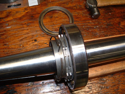
 The crankshaft goes in next.  I bought a new bearing.  It's a stock bearing, still made today - identical to the original.  Buying this bearing is one of my favorite stories...once I determined the number, I shopped around to find the best price.  Believe it or not, Amazon had the best price.  I ordered the bearing for a 100 year old OX-5 and the movie The world's fastest Indian - all on the same order.  It is amazing how times have changed!
Main bearing cap

Timing marks on camshaft gear and crankshaft gear

Completed installation with bearing caps torqued

Don't forget the bevel drive gear for the oil pump!


I had to get the rod bearings re-babbitted, but the mains checked out great.  The clearances need to be .0015-.002".  Mine were all within these tolerances.


When the crankshaft is installed, make sure the timing marks are properly aligned.


Once everything is torqued and secured, the crankshaft/camshaft should rotate with no binding.  It's also important to make sure there is clearance between the camshaft gear and crankshaft gear, and that the thrust bearing will rotate in the crankcase.  This assures the crank is being supported by the main bearings and not the gears or thrust bearing.


Lapping in prop hub

Finished lap showing good contact the entire length 
This is also a good time to lap in the prop hub before the key is installed on the tapered portion of the crank.  I just use fine valve lapping compound, put some on the hub, and slowly rotate it around .  It's amazing how much better the fit is after doing this.  This also makes sure the nickel plating I had put on the hub did not reduce its ID any.


Valve spring compressor

Got a few things ready to assembly cylinders too.  I had new intake springs made (the exhaust were fine). I measured the load on all the springs to make sure they were in spec.  I also made a valve spring compressor to aid installation.  For this, I used a broken water pipe/rocker arm support and then made a handle to compress the spring.  What's nice about it is I can pull out the shaft that holds the handle, rotate it around, and install the other spring without unbolting the support.


Exhaust deflectors


Another mod many people do is to make an exhaust deflector to go under the exhaust spring.  The exhaust manifold has a deflector welded on it, but this will not protect the spring from loosing its temper if the gasket blows.  You could make these from many different materials.  I made mine from .032" 4130 so I could black oxide them.  I'll have better pictures to show how this works once the cylinders are assembled.


PHEW!  A long post.  The next one will probably be more sheet metal work on the airframe and OX-5 assembly.  Check back in a couple weeks.