Sunday, March 29, 2015

March 29 update - Cabane Struts

The annual is finished on the mighty Funk.  My annual inspections are pretty intensive - I don't do "paper annuals" on customer airplanes or mine for that matter.  Besides the annual, it got a good wax job to brighten up the Randolph dope.

When I got back on the LP, it was a lot of head scratching and layout.  I first dug the fuselage out of the corner of my hangar.  I was curious how straight it was.  When I got it leveled longitudinally and laterally in front and checked it at the tail, it was mostly level or no more than .1 degree off.  The wing mounts were also level.  This was all very encouraging!

Fuselage leveled and checked for straightness

It was then time to start thinking about cabane struts.  I have no struts, only OX-5 Swallow drawings from which the LP is a close copy.  

When Victor Roos left Swallow to go to Lincoln-Page, he took with him the OX-5 Swallow design.  That is why the airplanes resemble each other.  However, the airplanes are different in many areas.  Unfortunately, all the LP drawings were apparently destroyed in a flood.  A very interesting letter I have in my collection is from Victor Roos's wife.  When Andy bought the airplane from Chuck Balling (the original owner) in 1966, he tried to acquire information and wrote to Mrs. Roos.  I find the letter very funny as she has "neither time or inclination to look over files of old documents..."!  By the way, the letter is addressed to Ken Ward.  Ken was a neighbor of Andy's who helped research things with the airplane as Andy was busy with his career at United Airlines.

Letter from Hazle Roos - Victor Roos's wife

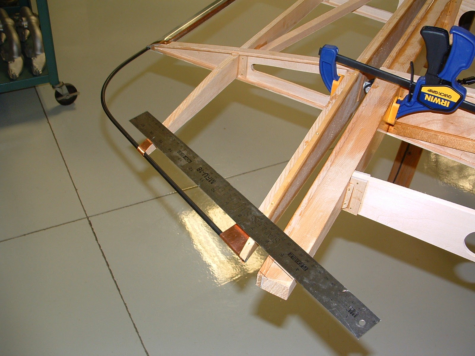
Back to the cabanes...I tried to do all the layout by using trig functions, but wasn't getting a good feeling that things were working out OK.  I decided to make wood cabane mock-ups so I could take hard dimensions off the airplane.  A much better approach! I started with the Swallow dimensions and in the end, those numbers came out very close - even with the angle of incidence of the 2 airplanes being different.

Mock-up of cabane struts

There are only 3 variable that can be controlled/adjusted with the cabane struts:  stagger, gap, and angle of incidence.  For the LP, these specs are:
  • Stagger - 29% positive or 16 degrees
  • Gap - 60 inches
  • Angle of incidence - 1 degree upper wing, 1.5 degrees lower wing (not adjustable)
My friend Mark came over to help, and with levels, plumb bobs, etc., we got it worked out.  So I now have all the strut lengths for the cabanes.  Streamline strut material is on order, and will be made once that material arrives.

In the meantime, I'm going over the fuselage with a fine-tooth comb.  Adjusting and correcting all attach points, tubing, etc that is bent or tweaked.  In addition, I'm adding more stand-offs on the tubular metal stringers to keep them from bowing in as the fabric covering is shrunk.

It will probably be a couple more weeks until the next update - there is just a lot more thinking and less doing going on right now!

Saturday, March 14, 2015

Upper Wings #10 - Wings Done!


Holy Bernoulli equation, Batman - the upper wings are done, actually all the wings are done!

Left upper wing

Right upper wing


It took almost 18 months to the day, to build these - what a relief.  This has, and will be, one of the biggest tasks of this project as everything had to be made new.  And, I would still be working on them with not all the help from Andy and his son Dennis making all the ribs - Thank You!

Prior to finishing them, I had to complete a couple of things - ailerons and tip bow.  Here's how that went:

Ailerons

Marking rib alignment of wing to aileron


I started by attaching the aileron spar to the trailing edge of the wing, aligning it in it's final, installed position.  This way I can be sure the ribs on the aileron will align perfectly with the ribs on the wing.


Gluing main ribs in place


Next is attaching main ribs to spars.  Plastic food wrap underneath keeps parts from sticking to bench as glue dries!
Trailing edge ribs and capstrips installed


Install trailing edge ribs and capstrips.
Trailing edge installed


The aileron is then reinstalled on the wing to attach the trailing edge.  This assures it is in alignment and straight with the trailing edge on the wing.


Tip bow with copper strapping


 Finally, the tip bow is installed - 1/4" 4130 tubing with copper strapping as per the original.


Here they are, completed and varnished.


Wing tip Bows

Marking location of wing tip bow to aileron tip bow


 I wanted to make sure there was a nice transition and alignment of the aileron tip bow to the wing tip bow.  So, I installed the aileron and marked the rear spar where the 3/4" tip bow tubing would attach.
Bending tip bow


The bow is made from 3/4", .028 wall 4130.  With this thin wall, the tubing can be formed with a conduit bender.  You just have to go slowly to avoid kinking the tubing.  I had previously made a template so I knew how much to bend the tubing.

By the way, many aircraft of this era used a laminated wood tip bow, the Lincoln-Page used the tubular type like I made here.
Final alignment check


Here, I'm checking alignment after the tubing has been curved and the spars drilled to accept the tubing.


Completed tip bow


I realize I'm skipping a lot of steps here, but here it is installed with the mounting brackets welded in place, wood cross supports attached, and painted.


Once these 2 things were completed, I could put the final coat of varnish over the wings and jump up and down and celebrate in my hangar like a mad man (OK, I really didn't do that!)

With the wings done, it's time to shift gears.  I need to temporarily mount the wings to the fuselage.  This will allow me to make all the struts, make and run all the cables in the wings and measure lengths of all landing/flying wires to order when ready.  I'm going to start by making the cabane struts.  This will allow me to set the top wings in their proper position with respect to the bottom wings.  With no center section, this complicates rigging a little, but does eliminate a whole other component.  Then the lengths of the remaining struts and streamlined wires can be determined.  None of the struts survived over the years with this project.  So again, as with the wings, they will have to be made from scratch.

First, I'm going to take a little time off from the project to annual the Funk.  With the weather finally in the 50's and 60's it's time to go flying!

Check back for an update - other than wings finally - in a couple of weeks.


Wednesday, March 4, 2015

Upper Wings #9 - Leading Edge

Leading edge installed - very close to having the wings done!

With this step finished, all that's left is the tip bow and varnish.  Here's how the leading edge went:


Glued up scarf joint
 When I did the bottom wings, I had some spruce boards long enough for the whole length.  For the upper wings, I didn't.  Being the tight-wad I am, I took some shorter boards and spliced them together with a scarf joint.  Perfectly acceptable, in fact it can even be done on spars.

Here you can see one of the scarf joints on a 1 3/4" X 3/4" spruce board.
Spruce board glued to nose ribs


It was then glued to the nose ribs, and I marked the end with a template of the final contour.  A #4 X 1" brass screw went through the leading edge and into each main rib in the wing.  This is how the original leading edge was installed.


Hand planing to shape


I then used a hand-plane to start shaping the leading edge.  A lot of work, but I like doing it this way as I can keep it straight as well as blend it in properly with the nose ribs.


Sanding block used for final contour


Once planed, I use this sanding block that has the correct profile of the leading edge.  This made sure the final shape was consistent the whole length and smoothed it up for varnishing.


Finished leading edge


Here is what it looks like after the final sanding.


You can see in this picture how nicely the scarf joint blends in after planing and sanding.


Before I finish the tip bows, I want to make the ailerons.  I do it in this order to make sure the tip bow blends in nicely with the aileron on each wing.  The ailerons go together quickly.  I made components for all 4 ailerons at the same time, so it's just a matter of putting the pieces together.


Other stuff...

I had gotten an early Scintilla eight cylinder magneto.  Since I've been in "magneto mode" I decided to go through it.  It's a Scintilla GN8-D1, an aircraft magneto designed for engines with a 4" or larger bore (that's what the "G" indicates).  Suitable for the OX-5, but the OX-5 was not designed to drive this magneto.  It has a 4-pole rotating magnet which fires 4 times per rotation.  This means it has to rotate the same speed as the engine in order to fire 8 times in 720 degrees of rotation.  The original Berling is a 2 pole magneto which has to rotate at 2X engine speed in order to provide 8 sparks per 720 degrees (only fires 2 times per rotation).  So in order to use the Scintilla, I'll have to design and make a gear box with a reduction.  It's something I'm going to play around with, but still plan on using the Berling initially.

There are a couple of things about the Scintilla that do intrigue me:  it has an impulse coupling, which will make starting the OX-5 easy, and Scintilla mags are an exceptional piece of equipment - the engineering, manufacturing and operation are some of the best out there.  As an example, the distance between the rotating armature and pole shoes in the housing is .002"!  This makes for a very low coming-in speed.


Scintilla GN8-D1 with impulse coupling


Here's how it looked initially. the armature was stuck, the impulse coupling didn't work, and the spring for the contact breaker assembly broken.


 I won't go into the details of the overhaul, but just show some final pictures.  I was able to get everything repaired and I will say it lives up to the Scintilla quality.  Just turning it over by hand produces a spark!

So we'll see what I do with it.  As I said, it will need a gear box to be used on the OX-5.  Not an impossible task, but just not a high priority right now.


Next - I'm going to build the ailerons for the upper wings, make/install the wing tip bows, and apply the final coats of spar varnish.  This should all be wrapped up next week.  The college I teach at will be on spring break, so I'll get lots of hangar time!