Saturday, April 25, 2015

Streamline Tubing and Cabane Struts


The cabane struts are done!


I'll go into a little on how they were made, but first, I mentioned in the last post I would talk some on streamline tubing.

One of the very cool things (at least for me) when restoring old airplanes, is to learn the history - not only of the particular aircraft, but the materials and how things were made.  In my research on streamline tubing, I found that 2 types were available:  Kawneer and AN tubing.  Kawneer tubing has a welded trailing edge.  So, I assume it is made from a flat sheet, rolled into an airfoil shape, then welded along the trailing edge.  My Funk that was made in 1946 uses Kawneer tubing for the struts.  I'm not sure how much longer after that it was available, but it must have been phased out soon after that.

AN tubing - the type that is also used today - starts out as round tubing and is roll-formed into a streamlined shape.  Seems like a better, easier approach to make it.  If you have purchased any, though, manufacturer's are very proud of it - expensive!!

I should mention one other type of streamline tubing that was used primarily in the WWI years that is somewhat odd.  It used several round tubes with progressively smaller diameters that were notched and nested together.  This gave a rough airfoil shape that could then be covered with fabric - interesting...

You've read in some of my other posts that the LP is close copy to the OX-5 Swallow.  Since I had no original cabane or N-struts, I made the assumption they were made the same as the Swallow which used Kawneer tubing.  Wanting to keep things as original as possible, my mind immediately started to think on how I could make Kawneer tubing since it was no longer available.  I actually took some AN tubing, cut the trailing edge, squeezed it to a sharp point and welded it.  Looked good, just like Kawneer tubing, but I couldn't get AN tubing that would give me the correct final dimensions of the Kawneer tubing.  RATS!

Then I got looking at my landing gear legs which used streamline tubing. I was always under the impression that Andy had these repaired after the accident in 1929 with AN tubing since it wasn't Kawneer.  I had Andy stop by and look at the gear legs and he said the tubing was original.  Now, this got me thinking...the gear tubing and strut tubing appears to be the same size in all the photos.  Why would a manufacturer stock and use 2 different types of tubing that are the same size?  So, I've made the assumption that the LP used AN streamline tubing.  The exact same size is still available today.  Right or wrong, this seems to make the most sense, and I think I have a better chance of being more right than wrong!

How they were made...

I showed in the last post how the adjustable ends on the diagonals were made.  There were 2 other ends that had to be fabricated.

Rear cabane strut
The rear strut, to which the diagonal attaches, required a special end/fitting.  All of the struts attach to a .200" thick tab on both the fuselage and wings.

In this photo, the finished strut is on the left.  The one on the right, shows the fabricated end that is slid into the strut and welded in place.  It includes the mounting tab for the diagonal and an internal pocket for the mounting tab on the fuselage to attach.

End view showing pocket for mounting tab


Here you can see the internal pocket for the mounting tab on the fuselage to go.


Strut has been slit ready to receive bushing and extension


All the other ends were a little easier to fabricate.  Basically a bushing with an extension welded to it to distribute the load.  The following pictures tell the story...

Using mounting tab and punch to align everything prior to welding

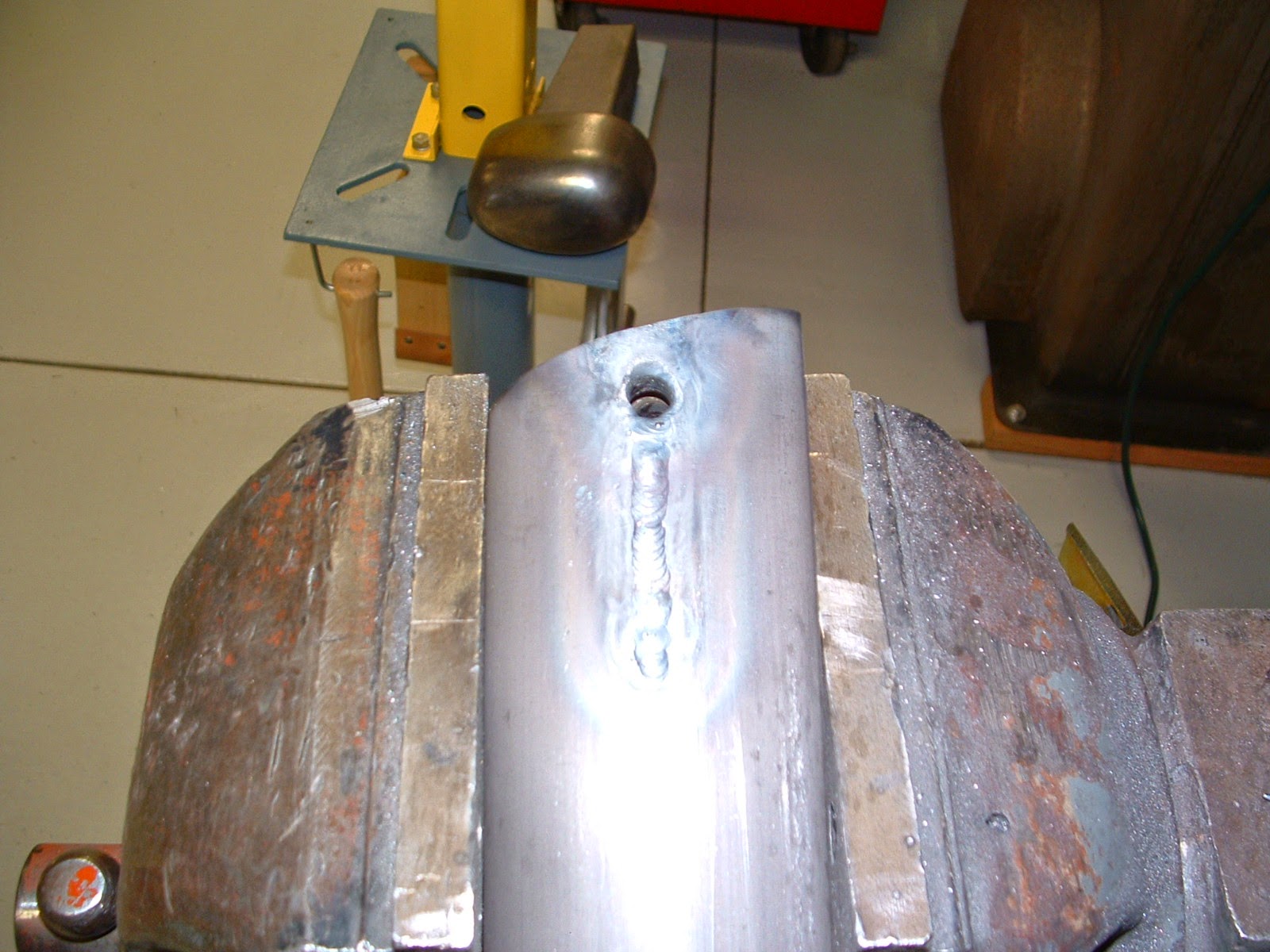
Extension on bushing welded and bushing welded to hole in strut

Finished assembly


Bead blasted fuselage
Besides finishing the cabanes, I got the fuselage and tail surfaces back from the bead-blaster.  They came out great with little evidence of corrosion.  I've been wanting to epoxy prime them, but have too much stuff in the way of my paint booth, so I need to spray them outside.  We've had a terrible cold/windy spell so I've been unable to do it.  This next week looks much better.

Bead blasted tail surfaces
Rotisserie chicken!!


My friend, Mark brought over this great rotisserie for me to mount the fuselage on.  He had it for car restorations he does and modified it to fit my fuselage.  I can rotate the fuselage 360 degrees with one hand - this will be so nice!


Hangar getting full!
And finally, my hangar has gotten a little more full.  I agreed to take on an interesting project - a 1931 Fleet Model 9.  The aircraft is owned by Mike George of the Air Combat Museum in Springfield, IL.  Mike has one of the finest collections of military and antique aircraft in the country.  If you are ever in Springfield, it is a must-see.  This particular Fleet is a rare one.  According to Juptner, only 25 were made, and apparently there is only one other flying.  Mike and I are unsure at this point how far I'll take this project, but I'm looking forward to working on it.  Don't worry, things will still be progressing on the Lincoln Page, just not as quickly as it has been.

1931 Fleet Model 9 fuselage
Next on the LP...it's time to mount the wings to the fuselage.  I can then build the Interplane struts, determine lengths of flying/landing wires, make the control cables, etc., etc.  It should look more like an airplane soon!


Friday, April 10, 2015

April 10 Update

I've gotten several misc. things done the past couple of weeks.  Much of the work has been on cabane struts.  I'll devote an entire post to those and talk about my streamline tubing dilemma when they are done.  Here are a couple of pictures, though, of the diagonals.

Fitting barrel into streamlined tubing


 The diagonals are the only cabanes that are adjustable, with a forked terminal on the lower end.  I welded in a conventional barrel and then slit and welded the trailing edge to taper it down like the originals.
Finished diagonals with old terminals installed for mock-up


I delivered the fuselage to a local bead-blaster this past week.  It will be done a week from today.  Prior to sending it out, I added some additional stand-offs to the tubular stringers.  This will increase the rigidity of them and help to keep them from bowing in after the fabric covering is shrunk.

Fitting stand-off


The proper length of stand-off was cut to fit between the stringer and structural tubing.
Shown after welding


I then gas-welded them in place. A big improvement as some of the original stand-offs were several feet apart. Now, most about 1 foot apart.


There are strips of steel with threaded studs welded in that run on the upper longerons from the front to the rear cockpit.  These allow attachment of the sheet metal that goes around the cockpit openings.  Most of the threaded studs were in poor condition so I made new strips.

Old and new cockpit sheet metal attachment strips

Finally, some things are happening with the OX-5 again.  One of the issues I wanted to address were the pistons and rings.  The originals have 2, very fat compression rings with no oil ring.  In order to use them, I would have to have custom rings made, or put 2 rings in each groove.  I was not really happy with either option.  I have to think these fat rings cause a lot of friction, plus offer no oil control.  

I asked around, and found out that a company in California called Egge makes custom pistons and have made them for the OX-5 before.  Egge is well known in the hot rod market for flathead Ford and other engine parts.  I was concerned they would not be willing to make anymore aircraft engine pistons, but they were more than happy to.  I sent them dimensions, and with only a 5 week lead-time, got them last week.  They are a thing of beauty (only a true gear head can get excited about pistons!)

These pistons use 3 conventional automotive rings; 2 compression and 1 oil control.  This should be an overall improvement - less friction, higher compression and better control of oil.  Apparently, even in the early days of the OX-5, overhaulers realized the value of this type of piston.  There were aftermarket manufacturers of 3-ring pistons that offered an additional 75 RPM, more than likely due to less friction and better compression.

New piston on left, original on right

Inside view

Here you can see the difference in ring thickness.  Original on left
with 2 fat rings, new on right with 3 standard automotive rings

Next... I am going to finish the cabanes, and put some DP epoxy primer on the fuselage when I get it back.  Check back in a couple of weeks for the next update!