Friday, December 26, 2014

OX-5 Valve Guides

Since my friend Mark and I like working on old engines, and we were getting a little stir crazy from the Holidays, we decided to see how the valve guides would go.  It went extremely well, but a little background first.

An early method of replacing valve guides
The OX-5 cylinder is one-piece (no separate head) and is made from a single cast iron casting.  The guides are also integral to this casting.  This makes guide replacement more involved than more conventional ones that are removed when worn out and replaced with new.  Early companies like the one shown to the right and others like Miller made replacement guides.  The old ones had to be machined out, the hole threaded and then new ones screwed in.  This required careful fixturing to ensure the new guide was somewhat concentric with the valve seat.

Fortunately, there are better methods available today and the one I chose was to use guide liners.  The challenge, though, with liners is again keeping the lined guide concentric with the seat.

In most automotive applications, the guide can be machined from the seat side to accept the liner.  There are centering tools available to keep everything concentric.  With the OX-5 and other aviation engines, the machining has to be done from the valve spring side.  This is because the head and cylinder are integral and the valves sit at an angle, so the machining can't be done from inside the barrel.

Modified reamer with pilot and centering cone
Here's a picture of what I made to ream the guides to fit the liners and keep them concentric with the seat.  I first obtained a reamer of the proper size to fit the liners.  I had the tip ground to fit a long pilot that was pressed over the end.  I then made a cone with a  bushing pressed in the center. The cone sits in the valve seat and keeps the reamer concentric with the seat as it is being reamed.  Some pictures farther down in this post will make this easier to see.

K-Line valve guide liners
Several companies make liners, and the ones I chose were from K-line.  These liners have a spiral groove machined on the inside for lubrication.  Since the OX-5 valves have to be manually lubricated, this feature is perfect.   The liners have a .015" wall, or in other words, fit in a .030" oversize hole.  The nominal OX-5 valve size is .375", so the holes are reamed to .405"


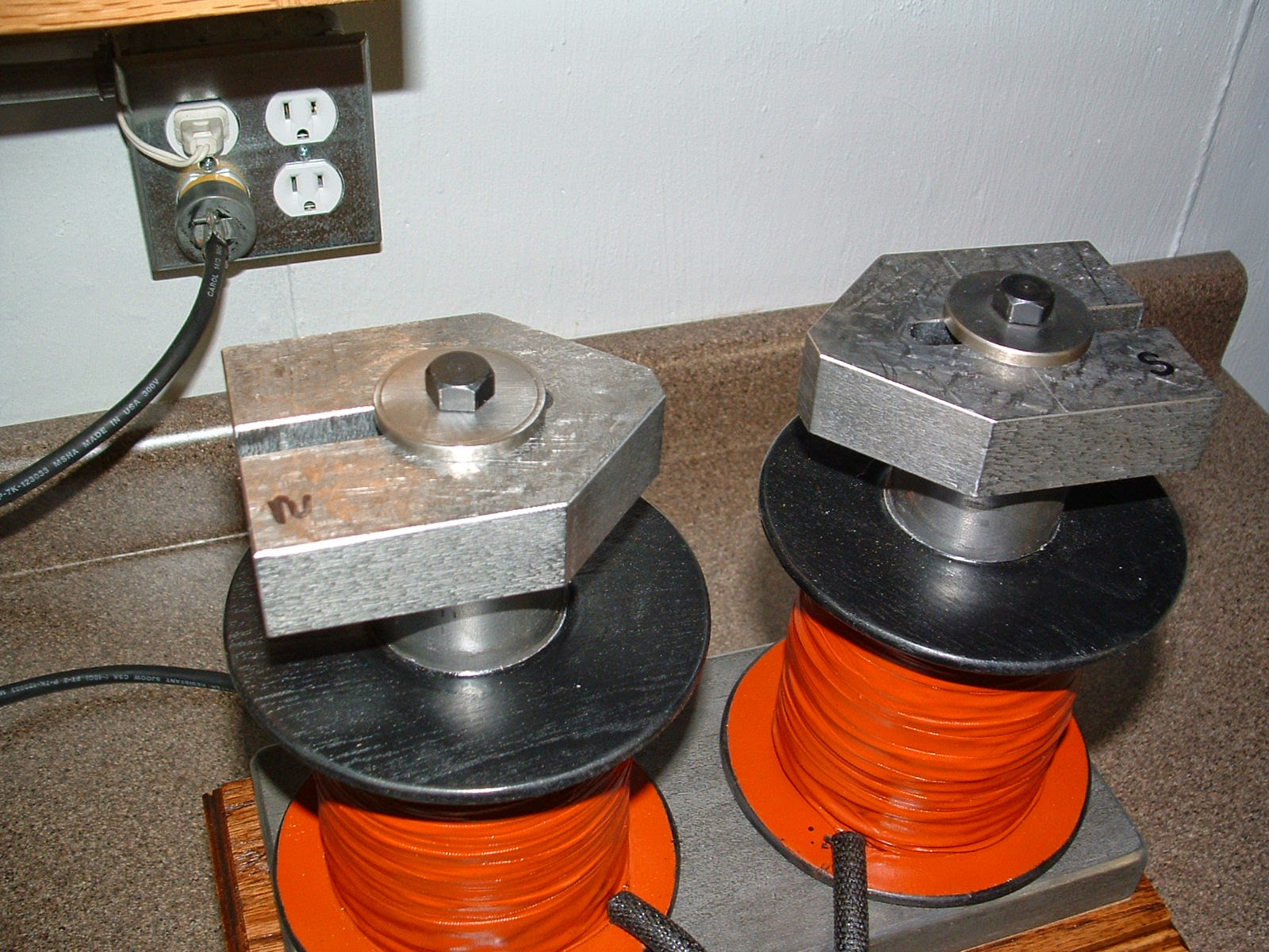
Tooling required for liner installation


There is some other special tooling required as seen in this picture - probably best to describe them as I go through each step.


Step 1:  Ream the guide
Guide reaming

Here you can see how the reamer is inserted in the guide from the valve spring side, with the pilot going thru the guide and into the centering cone.  


Liner insertion
Step 2:  Insert the liner

A short stroke rivet gun and a special insertion tool is used to press the liner in the reamed guide


Liners after insertion
The liners are longer than needed, so after insertion they have to be cut even with the guide at both ends.


Sizing the liner with a carbide sizing ball
Step 3:  Sizing

The liners then have to be sized.  This does a couple of things:  Allows for proper fit between the valve and liner, prevents the liner from getting loose in the reamed guide, and allows for heat transfer between the liner and guide.  The sizing is done with several sizes of carbide "sizing balls".  Balls of various sizes are pushed thru the liner with a special tool and rivet gun until the proper valve to liner fit is obtained.  The dimensions of my valves required a .375 and .376 carbide sizing ball.  The ball can be run thru multiple times and each time, up to a point, the ID of the liner gets slightly bigger.

The liner is then lightly honed with a honing brush and the valve can then be checked for fit and proper sealing at the seat.

Finished installation showing internal spiral grooves

Now to the valves... As you may recall from my previous posts, this is a very low time engine.  My hope was to use the original valves, but I was unsure until I could get them cleaned up.  Well, they cleaned up great.
Original valve prior to lapping


Hard to believe, but here's a picture of an 86-year old valve that has not even been lapped yet.  Amazing!


Checking valve fit with bluing

Intake and exhaust valves after lapping
Now the moment we've been waiting for - is the liner concentric with the seat???

YES!  This whole process couldn't have worked out any better.  The seats and valves required no grinding, only a light lapping was necessary!

This was a relief, because if you're familiar with stock OX-5 valves, or see in the pictures, there is very little margin to do any valve grinding.

Every once in a while something just seems to come together nicely, and this was one of those times.  Thanks to Mark for all his help on this too.


Cleaned studs
 In a different, but OX-5 related topic, I got the engine studs black-oxided.  I bought a kit to do this myself and it is very easy to do.

The studs first have to be very clean.  I used a wire wheel to remove any corrosion.
Chemicals used for the blackening process
The parts are then put thru a 4-step process.  

1.  A cleaner to remove any grease and contaminates.

2.  A prep to make for a deeper oxide finish.

3.  The blackening process.

4.  A protective coating to improve the corrosion resistance.


Finished studs with black-oxide coating

I made a little basket to put the studs in, and about a 2 minute dip in each solution is all that's required.  Parts come out very nice looking and protected against corrosion.


Back on to the wings soon, but still waiting on capstrip material.  So, I'm not sure what my next post will be on, so stay tuned!


Friday, December 19, 2014

Upper Wings #6

Well, I got everything done mentioned in my last post.

First, I made all the bracing wires, painted them, installed them and trimmed each wing.


 I then got the nose ribs installed - lots of them!  38 on each wing!  That's Chuck Connors as the Rifleman on the TV in the background.  Chuck often keeps the hangar free of outlaws.


Then, the trailing edge ribs.  These go a lot quicker, not as many since this is a 4 aileron airplane.  

The upper wings are notched above the rear cockpit to make getting in and out easier.  That is why the 4 ribs at the root of the wing are shorter than the rest.


Next, I have to install the capstrips.  I had to order the 3/16" by 5/8" spruce material.  I doubt it will be here before Christmas, but that's OK.  Our Son is coming home from the Army, and there will be lots of family events going on.  I brought a couple of projects home to keep plugging away as time permits:  I'm restoring the ignition harness (I'll create a post on it) and I pulled all the studs from the OX-5 crankcase and applying new black oxide for corrosion protection.

Merry Christmas everyone - hope you all have a blessed holiday season!

Friday, December 12, 2014

Upper Wings #5

OX-5 cylinders with fresh nickel plating
To start things out, I got all the cylinders back from the plater.  Now all of them have a nice covering of nickel plating.  You can refer to a post I did this past October that explains the Watts nickel plating process used on these.

Next on the OX-5, while I'm waiting on the babbitt work, is to finish up the cylinders.  They don't need much.  The guides are a little sloppier than I like and will be sleeving those.  Stay tuned for a post on that.


Rib glue blocks installed - 1/4" triangular spruce.  The shiney spots
is varnish that has been applied that will be underneath the fittings.


Mostly it's been lots of wing work.  The pictures pretty much tell the story...


All the ribs glued in place

Varnish applied and all the fittings installed


I can already tell that doing both wings at the same time will be a big time saver.  I'll be adding the drag/anti-drag wires next, then the trailing edge and leading edge ribs.  Stay tuned to the same "Bat Channel" for an update in a week or so!


Saturday, December 6, 2014

Magneto Magnet Charger


Mark and I finished our magneto magnet charger (magnetizer) this week, and it is a thing of beauty!  I need to point out, though, that Mark did most the work.  He had the last couple of weeks off, did all the machining, and he and a neighbor made the beautiful oak cabinet.  It looks like a vintage piece of equipment, and with both of us liking old things - it's perfect!

This was not our invention.  In fact there are numerous specs on the Internet for devices like this.  Even old Dyke's automotive manuals from the early 1900's have plans.  We did have certain criteria:  we wanted a magnet charger that would generate about 12,000 ampere-turns - enough to saturate the magnets on just about any magneto magnet.


Our design has two 6 lb. coils of 18 ga. copper magnet wire wound on 2" steel cores.  The coils are mounted on a steel base that allows the flux to flow un-inhibited between the two.  Adjustable pole shoes at the top contact the magnets that are being re-magnetized.


Electrically, this unit runs on 115V AC (another reason we chose this design).  DC current has to flow through the coils, so a full wave bridge rectifier is used.  We installed a line fuse, added a light to know when the unit is energized, and an ammeter.  When energized, it draws about 10 amps.


Here's a picture of one of the Berling magnets being charged.  We couldn't have been more pleased with the results.  The magnet initially had a pull force of 6 lbs.  after charging, it had a pull force over 30 lbs.!  We got the same results when charging both magnets simultaneously, indicating we are getting adequate saturation.  The unit was only energized for 5-10 seconds.

An important thing to know, a keeper has to be used when the magnet is transferred from the charger to the magneto.  A keeper is just a steel bar, about the same cross-sectional area of the magnet, placed across the poles.  This allows for a highly-conductive path for the flux to flow.  If it has to jump an air gap, even for just a second, the strength of the magnet is compromised.  We tested this several times - a charged magnet would again pull about 6 lbs. after the keeper was removed.  

A better way to re-charge the magnets, and not mess with a keeper (which can be a challenge on the Berling because of how the magnets mount) is to re-charge the magnets on the magneto.  That way there is no transfer from the charger to the magneto and the keeper is not necessary.  The pole shoes on our unit allow for this, and can be changed if I'm doing a different shaped magnet.

So with this done, I can finish up the Berling overhaul.  I had it mostly complete, but came across a problem.  When I assembled the armature, I noticed it had a slight wobble to it.  I put it between centers in my lathe, and it had about .010" runout at the bearings!  I suspect it may have been like that all along.  My main disappointment, though, was this was an armature I had rewound.  I've got several Berling spares, so I grabbed another armature, put it between centers, and it was perfect.  The coil looked good and checked out fine, but I refuse to use an armature with 100-year old magnet wire on an engine that only has one magneto!  I have lots of coil winding experience in my previous work as an engineer and am aware that the polyester and other insulating materials used on modern magnet wire is far superior to what was used originally.  So, I sent it off for re-winding.  When it comes back, I'll finish up the magneto and put in a post on the overhaul.

I'm also making great progress on the upper wings and will update everyone on those soon.  I'm giving final exams Monday and Tuesday next week to our future A&P Mechanics and will then have a month off over Christmas break.  Unless we get bitterly cold like last winter, I should be able to get a lot done!

Until next time...


Saturday, November 22, 2014

Upper Wings #4 and other misc.

It's been a couple of weeks since I added a post, so I thought it was time to update on what's been going on.  I've made some good progress,  just not much to show for my time as it has mostly been time-consuming component work.  I decided to build both upper wings at the same time.  Should save time, but has added more work up front.

Here's what I've been working on the last couple of weeks...


Plywood strips have been cut and glued to the webs of the ribs.  Provides considerable strength since as you may recall, these ribs are made from basswood.


The spars have been drilled for all the fittings that will eventually be attached. The rectangular plywood pieces are where the aileron hinges attach.


These are the plywood compression ribs.  A 1/4" by 3/4" spruce strip has been glued on each side to give them the necessary compressive strength.


All the fittings that go on both upper wings have been painted.  Why black?  Well, the common aviation primer for many years was zinc-chromate, but was not yet available in the '20's, or if it was, not used in the aircraft industry.  If you look in old aviation supply catalogs from the '20's, like Nicholas Beazley, lacquers and enamels were readily available and used.  I can really find no signs of any paint on the original fittings, but certainly don't want to leave them bare steel.  So, with black being a common color, that is what I went with.  Plus it just looks right.


I also wanted to get the other 7 cylinders nickel-plated.  Most custom platers get pretty busy over the winter and I wanted to make sure these got done in a timely manner.  In this picture, the cylinders have been blasted to remove any old nickel and all the holes/ports plugged to keep the nickel out of unwanted places.


I have wanted to build a magnet charger for magnetos for a long time.  My friend, Mark also wanted one for the Ford Model T's he restores.  So, we decide to build one together.  He can use it on his Model T's, and I can use it on the Berling for the OX-5 and other mags I do.  This pictures shows the coils we recently wound, one with the motor-winding tape already wrapped around it.  When we have it finished, I'll put in a detailed post about it for anyone who may be interested.


Just about ready to start attaching ribs to the spars, that will probably be my next update in a week or so.  Hope everyone has a great Thanksgiving!


Friday, November 7, 2014

Upper Wings #3

The upper wing fittings are done...except for a few minor things like drilling holes for the wire terminal fittings and painting them.  Lots of cutting, grinding, filing, bending, welding, etc., etc.!!

Certainly better than the originals:  the originals were crudely cut out, and the new ones made from 4130 will have better strength properties than the low carbon steel previously used.

Detail pictures and descriptions of the fittings follow.

Weld detail


Most of the fittings have a doubler welded on the top to increase the thickness to .200" where the terminal fittings and struts attach.  These were all TIG welded which is my preferred method of welding. 


Cabane, landing wire - rear spar

Interplane strut and flying wire attach - rear spar

Cabane, landing wire - front spar

Interplane strut and flying wire attach - front spar

Aileron pulley brackets

Aileron hinge fittings

I'll get these finished up and painted in the next couple of days, it will then be time to start the actual wing assembly - Finally!

Tomorrow, we are heading up to Fond du Lac, WI for the annual Midwest Antique Airplane Club (MAAC) banquet.  Always a nice gathering and good time!  

Until next time...


Sunday, October 26, 2014

Upper Wings #2

Our final Fall camping trip


We have been having phenomenal weather this Fall, so we had to play hooky on the LP project and do one more camping trip.  Our daughter Melanie and her boyfriend joined us.  We had a great time!


Mark busy on the grinder

What little work I have gotten done has been on the fittings.  There are about double the fittings on the upper wings, so it's a major undertaking.  It will probably be a couple of weeks until they are all done.  My friend Mark, who's been a lot of help on this project, even gave up his day off - Columbus Day - to help with them.

Wing attach fittings


I started with the fittings that attach the two upper wing halves together.  Not difficult, just a lot of cutting and careful bending.  These are all made from .100" 4130. 


Upper wing strut fitting


I believe I mentioned in other posts that most of the upper wing fittings survived although not in great condition as seen with this one.  According to Andy, the wings were stored outside and a prairie fire destroyed portions of them as seen on this charred piece of rear spar.


Back to the shop tomorrow and starting on the cabane and interplane strut fittings.  Last Friday, my friend Mark and I drove my engine parts to Hart's Machine Shop in Ohio.  They will be doing all the babbitt work on the main and rod bearings.  Have not used this shop before, but left with a good feeling about them.  Several gray-haired employees with lots of antique engine experience.  A busy shop with a 6 month lead time!


Sunday, October 12, 2014

Upper Wings #1

Bottom wings are done.  Aluminum on leading edge
is just there to distribute the weight while in storage


With the bottom wings done and stored in wing stands, I'm getting a good start on the upper wings.  After doing the lower ones, it's in many ways like starting all over again.  All the fittings are different, and no wing walk area at the root of the wings.  Fortunately, the ribs, internal bracing, wing tip bow and ailerons are the same as the lower wings.


What's left of original upper RH wing


More of the upper wings survived the years of storage.  This makes for a little less engineering involved in figuring out angles of struts and wires.  Most of the fittings survived too, which will be useful as patterns.


Spars with rib locations marked


The spars for all the wings were made at the same time, so the first step was to lay out all the rib locations. Andy and Dennis finished all the ribs, therefore it's just a matter of gluing on the triangular glue blocks and attaching them in their proper locations.  But first, I need to make all the fittings and brackets to properly locate them on the spars.


Original cabane and wire fittings


Here's what I have for original brackets.  These will be useful for patterns, but that's it - none are useable.  All will be made from .100" 4130.  On some, it was fairly easy to flatten them out.  On others, I'll just take dimensions to duplicate them.


These are the fittings that attach the two wing panels
together in the middle (there is no center section)


It can't be all work and no play.  We've had great weather this fall, and the leaves are just about at their peak colors, so we took the mighty Funk out for some sightseeing.