Sunday, February 28, 2016

Curtiss OX-5 Overhaul Summary

The OX-5 is done, well at least as far as I'm going to take it for now.  Only a few more water and oil lines and install the carburetor.  I'll probably wait until I hang the engine to finish up these last few items.

All this has been covered in previous posts - you can refer to them for more details - but I thought I would summarize the overhaul in one post.

To recap the specs:  

  • Serial Number 5094
  • Built by Curtiss (not a licensed contractor)
  • Date of manufacture:  1-19-19 (according to Lincoln-Page documentation)
  • Less than 100 hours total time since new
  • A completely matching numbers engine 


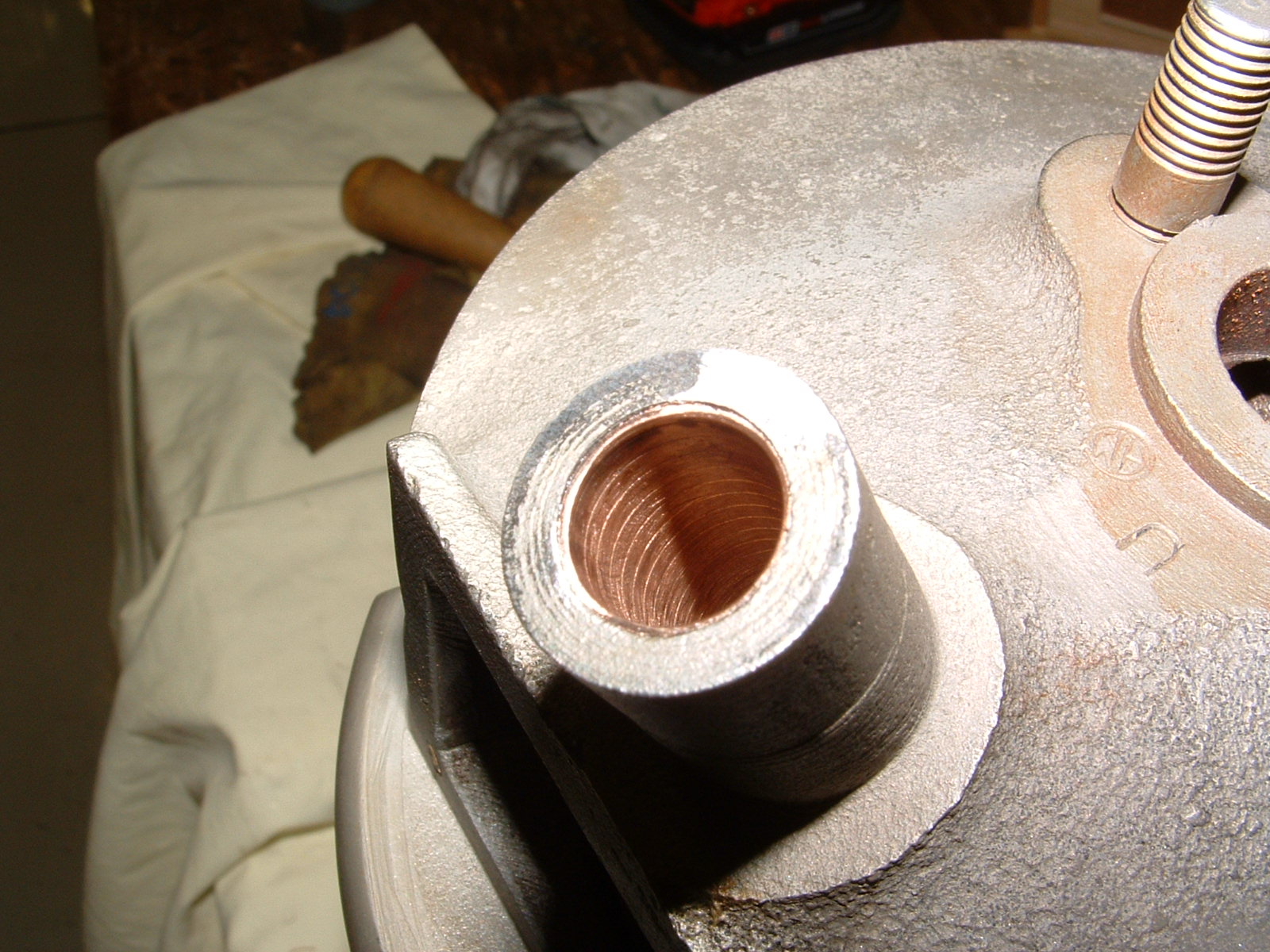
Here's what I started with.  It had been in storage since 1929 when the aircraft was wrecked, but well preserved.  Everything cleaned up great with no corrosion concerns.


All the aluminum components cleaned up great.


The crankshaft polished out beautifully.

 The crankshaft could now be fitted to check main bearing clearances.  These checked out great with .0015" clearances.


 The rods bearings had to be re-babbitted.  I also had the small end modified to accept a bushing for a full-floating piston pin.  All this to accommodate a new set of pistons that use standard automotive rings.

New piston on left, original on right


 All the major accessories were overhauled like the water pump, carburetor and Berling magneto.


 The cylinders were reworked with new valve guide liners and the valves touched up.


The cylinders were then nickel-plated like the originals.


....and then finally assembled with the intake and exhaust valve springs.


 I obtained Miller overhead to replace the stock.  These components were rebuilt and the steel parts nickel-plated like the cylinders.


Assembly could then begin...


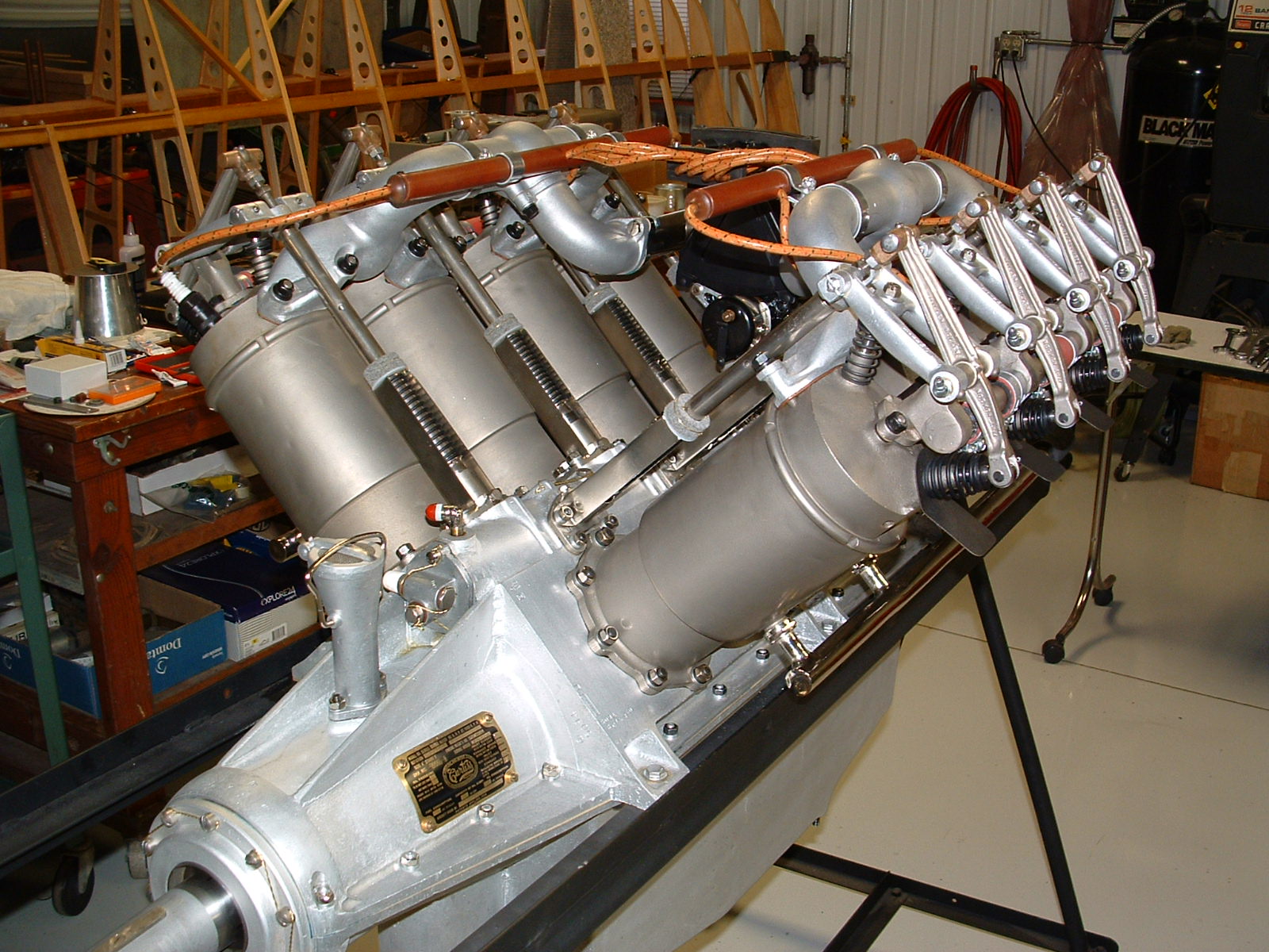
And here it is, mostly complete and ready for installation!

This was a fun engine to overhaul, and it looks great with the nickel-plating and natural aluminum.  Now, we'll keep our fingers crossed and hope it runs as good as it looks!

So, there probably won't be anymore posts on the OX-5.  It will be full speed ahead on airframe work.


Thursday, February 25, 2016

Gas Tank

You might be familiar with, or have even used the expression "if they made it that way 100 years ago, we can do it now."  If I've learned anything working on old airplanes, it's that this is not always true.  Todays manufacturing environment demands low labor costs with production efficiencies.  Just look at the complex ways things were made long ago.  Companies would not think of doing it that way today!  In 1928, labor was cheap and they built equipment and machines to do just about anything.

The gas tank I just completed is a good example.  This was one of the more difficult things I've ever had to fabricate.  It would be interesting to go back in time to 1928 and see how Lincoln-Page made it.  Fortunately, my friend Mark helped out a lot.  The size of the metal sheets and overall size of the tank made it about impossible for one person to manipulate.

Original tank - 40 gallon capacity

Interior of metal skins showing corrosion

New metal skins and baffles
 Here you can see what I started with.  I initially thought it may be useable, but after looking inside with a borescope there was too much corrosion.
Close-up of baffles


After taking it apart, the level of corrosion was very evident.  Once apart, the old skins could be used as patterns for the new ones.


New metal skins were cut out from 22 ga. galvanized steel.


There are 2 internal baffles that prevent the fuel from sloshing around too much.  These are held in with rivets.


The fore and aft portion of the tank

Baffles riveted to the side and top skin

Side/top skin being fitted
 As you can probably tell in the pictures, the tank is made from 2 pieces of sheet metal that are curved and held together with a seam.  So the first step was to form a 90 degree flange and a bead on the fore/aft skin.  This was done on my bead roller.
Fore/aft skin being fitted

Almost there!


A 90 degree flange was then formed on the side/top skin.  The baffles could then be riveted on.  The rivets are steel as they have to be covered with solder once the tank is complete to prevent leaking.


The 90 degree flange makes curving the sheets virtually impossible without kinking the metal.  It took lots of careful stretching in the stretching machine to get this piece to curve around correctly.


Just the opposite on the fore/aft skin as it required shrinking to curve correctly.  Had to work a little bit at a time here - a little shrinking, then fitting followed by more shrinking and fitting, etc., etc.


This is about as far as we took it.  Too much shrinking and stretching puts a lot of stress on the metal and I wanted to avoid any cracking.  Hand-fitting from here.


Rivets soldered over to prevent leaking

Ok, so I'm skipping a lot of steps here.  Believe me, it was not pleasant!  Getting all the flanges and seams to line up correctly was difficult to say the least.  the 90 degree flange of the fore/aft skin is formed over the side/top skin by rolling it over 180 degrees.  This was done by hand with a hammer and dolly.

Prior to assembly, the edges were tinned with solder.  Once crimped, more solder was added to make a nice, tight, leak-proof joint.  The baffle rivets could then be soldered over and all the other attachments soldered in place.
Filler neck and gas gauge mount soldered on


Here you can see the filler neck and mounting flange for the gas gauge soldered on.  The filler neck is a Ford Model "T" radiator filler neck.  It uses a threaded radiator cap as a gas cap.
Fuel outlet riveted and soldered


Here's the fuel outlet.  It was riveted first, then soldered as it has to withstand more stress when attaching the plumbing.


All done!

Here's the final product.  In spite of the grief it gave me in building it, I'm pretty happy with how it came out.  It was built exactly like the original.

 I still need to leak test it - screw on the cap with a good gasket, cover the gas gauge flange and attach an air hose coupling to the fuel outlet.  Pressurize the tank to a couple of psi, spray some soapy water on the flanges and hopefully, no leaks.  Probably not too big of deal if there is, just more heat and solder.


Besides the tank, the OX-5 is mostly done.  I'll do a final post on it soon.  For now, its back to airframe work in earnest.  Please check back soon...


Sunday, February 14, 2016

Berling Magneto Install


I thought I would have the fuel tank built by this post, but it didn't happen.  I've been playing a lot of hooky from the shop lately, and when I have been there it's been focussed on the OX-5.

It was time to finish testing and install the magneto.  I thought I would devote this post to step-by-step installation of the Berling magneto and some important things to watch.


Running on the test stand

Screw that locks moveable breaker contact
 I wanted several hours of run-time on the test stand prior to installation.  Early manuals call for 15% over rated full power.  The OX-5 is rated at 1400 RPM, the Berling operates at 2X engine speed, or 2800 RPM.  15% more is 3220 RPM. 

 After about 2-1/2 hours, several of the contacts quit sparking and kept getting worse.  When I removed the breaker cover, the points were closed!  Not sure what happened, I readjusted them and after about 1/2 hour it happened again.  I discovered the screw that locks the moveable breaker contact from turning has to be very tight to lock the contact.  I was not getting it tight enough, so the contact moved closed over time.  I have about a half-dozen other contact assemblies, and all of them had screw slots that were very worn and stripped.  Makes you wonder how many OX-5 powered airplanes went down because of this very reason!?


New lock screw on right, 6-48 thread


The screw is an odd size, a 6-48 thread.  Fortunately, this is a common firearm size so they are easy to come by.  The newer screws have a nice deep slot which makes tightening them easier.

New lock screw installed in breaker assembly.


Once the contact was properly locked, I got about 6 hours of run-time with no other issues.  I feel pretty good about using this mag, although regular cleaning and inspection will be necessary.  Berling made this easy as getting to these critical areas can be done in seconds.


Then it's time to prep the mag for assembly.  The first thing to do is install the drive coupling.   The drive lugs on the magneto side, couple to drive lugs on the engine side that are cushioned with what the Berling parts catalog calls "shock absorbers".  Obviously, after sitting for nearly 90 years, mine were dried out and hard.  I chose to make new ones from urethane - a very resilient rubber-like material that is oil resistant.  It's often used as die springs in punch press dies.  I made them from a 60 shore-A durometer which seemed about perfect.

Cutting out the center with a hole saw.

Followed by cutting them into segments.  An old one
is shown on the left.

Drive coupling installed


The drive coupling can then be installed on the mag.  It is held on with a nut, locked with a screw, and the screw safetyed with a locking clip.
Studs that locate mag on mounting plate


4 studs are then screwed into the base of the magneto.  These don't secure the magneto, just position it and keep it from moving around on the mounting plate.


Locating distributor segment for cylinder #1

Positioning distributor finger over this segment


The mag then has to be set so the distributor finger is ready to fire cylinder #1 as the points are just opening.


Aligning timing marks on drive gear and cam gear 
Magneto drive gear bearing
Slide the magneto into position, aligning the timing marks on the magneto drive gear with the cam gear. 

Fortunately, mine was stamped which made timing very easy.  The timing is set at 32 degrees BTDC.  Checking with a typical magneto buzz box, it came out perfect.  Make sure you do this with the advance lever in the full-advance position.

can't begin to guess how many magnetos I've installed.  This was by far the easiest - no adjustments required.  Not bad for 100-year old technology!


You'll also want to make sure you install the drive gear bearing to hold everything in position while you are checking the timing.


Hold-down strap installed which secures the magneto

Oil retaining cover with new felt seals

Cover properly secured
The magneto is secured with a hold-down strap.


Then, a pair of oil retaining covers are installed over the magneto drive gear.  These have felt strips that prevent oil from leaking past the shaft.  I made new ones from wool felt.


The screws to secure these covers are unique.  They are like a fillister-head, but the heads are square as you cannot get to them with a screwdriver.


Rear cover and tach drive installed


The rear cover and tach drive can then be permanently installed.  Early photos show the single wire method of safetying with 22 ga. soft steel galvanized wire.  That is what I used. 

Note, the tach drive is not safetyed yet as I'm not sure of the orientation until I run the tach cable.


Harness installation


Finally, the harness is installed.  I used all original components: the tubes, terminal ends, etc. Only the wires are new manufacture, cotton covered, lacquer coated, 9mm spark plug wire.


Original cable clamp


The cable clamp is also an original part.
I expect the engine to start very easily.  The Berling magneto is a very "hot" magneto which is typical of rotating coil magnetos vs. the more modern rotating magnet magnetos.  I found this out the hard way - just slowly turning the shaft slowly over with my hand over the distributor block gave me quite the shock!

While on the test stand, I checked the coming-in speed.  It was 70 RPM at full advance and 220 RPM at full retard.  This is excellent!  Remember, this magneto operates at 2X engine speed, so at full advance, the magneto is fully sparking at 35 engine RPM.  Quite remarkable!

Fuel tank done by next post - maybe...Check back in a could weeks to find out!