Sunday, April 24, 2016

Throttle and Radiator Shutters

Hi all - I've been picking away at some of the small details the past couple of weeks, specifically the throttles and radiator shutters.

First the throttles:

Original throttle control rod
The Lincoln-Page was WAY ahead of its time (not seriously!).  It came equipped with mounts for the throttle levers on both sides of the cockpit.  This particular airplane came from the factory with them on the right.  Probably because the throttle lever on the carburetor is on the right and not reversible.  The Zenith carburetor on the OX-5 can be  operated from either side, but it's a different lever.  This being the original carburetor and engine for this airplane possibly explains this.

I prefer the throttle on the left in tandem seat airplanes, so that is where I decided to put it.  This meant changing the controls firewall forward, but the rod back to the levers could remain as original.  The photo above shows this rod.  The short section attaches to the front throttle lever so the two are slaved together.

New throttle levers and control rod


 For the firewall forward portion, I had to come up with a torque tube that ran from the left side to the right side with a bell crank and rod attaching to the throttle lever on the right side of the carburetor.  Whew,  hope you can follow that!  The pictures should explain better.
Control rod attachment to torque tube

Torque tube attachment on RH side

Attachment to carburetor lever


When all completed, it came out great with very smooth action and nice travel range of the levers.


Radiator shutters:

The next major item to get sorted (as our British friends would say) was the radiator.  I put in an interesting post on the radiator in December 2015.  It's worth reading if you haven't already.  I still, though, had to fabricate the shutters and control mechanism.

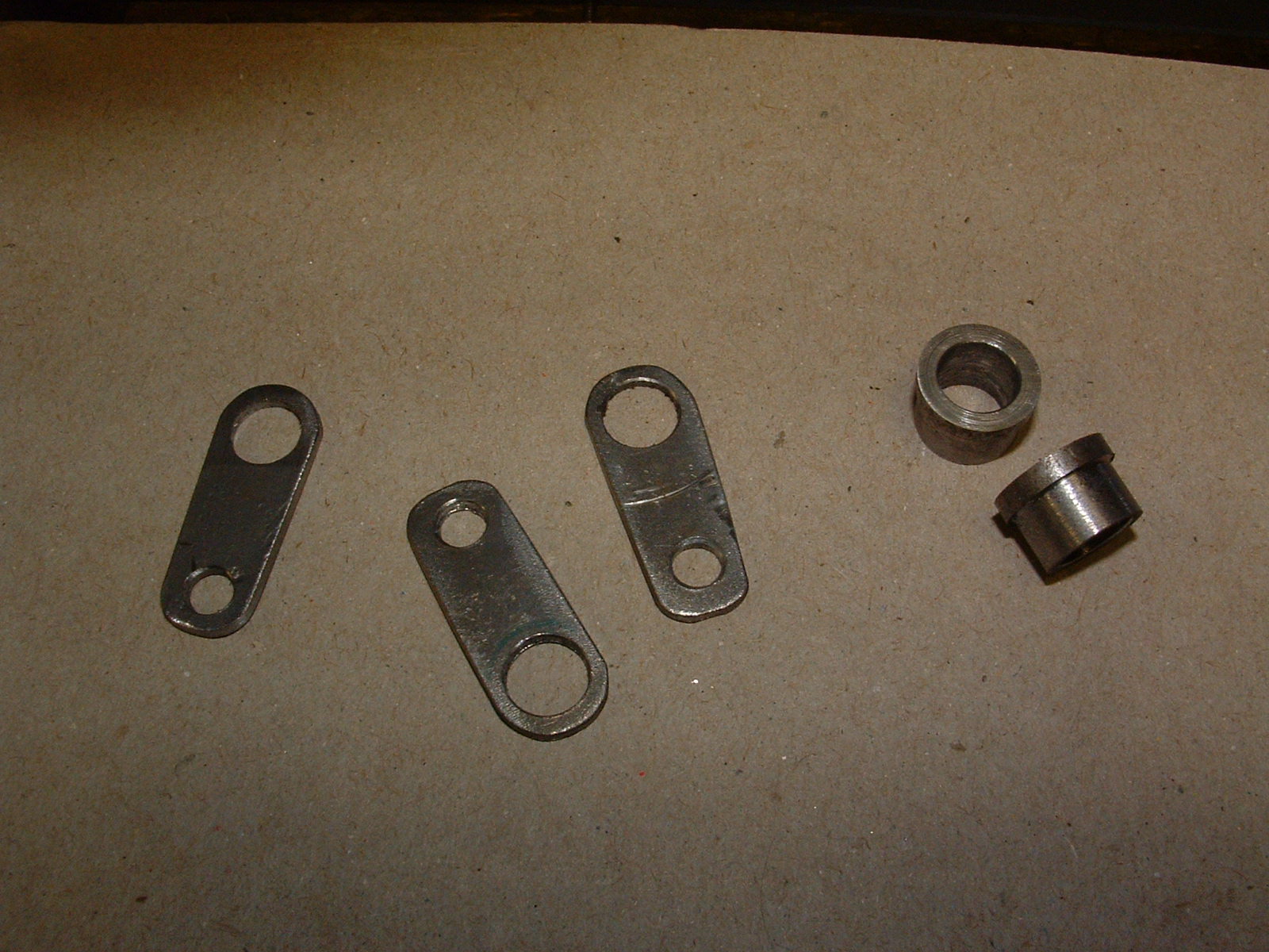
Levers and bushings for shutter rods

Levers welded to shutter rods


 The first thing to make were all the little linkages, levers and bushings to mount the rods for the shutters...
Completed shutter rods

Using tinners rivets to seal up ends of the shutter rods


I like to seal up the ends of tubing to prevent corrosion.  A neat way to do it is with steel tinners rivets.  They fit nicely in the end of smaller steel tubing and then are easily welded in.


Shutters closed
Shutters open

Shutter linkage
Then it was time to make the shutters.  Sorry, no detail photos here, but pretty straight-forward to make.  They are kind of a squashed diamond shape with the rod running down the middle.  They were all bent on a brake with a hemmed edge closing up the ends.


The end caps, that had to be fabricated as well, contain the linkages that operate the shutters and connect to a control lever in the rear (pilots) cockpit.  The bushings previously talked about are brazed into these end caps for the shutter rods to operate smoothly.


Next, I need to come up with covers for the top and bottom of the radiator to protect the core.  Then, mounting straps to hold the radiator to the bottom of the engine mount.  A control cable to the cockpit lever can then be run.

Things are taking shape - slow but sure!

Also, we are making a big push this year to get our current hangar sold so we can relocate our shop.  I realize many readers are too far away, but for those here in our region, it is one of the nicest hangars you'll find.  Located at C55 airport in North Central Illinois not far from Rockford.  It has a full bathroom with small apartment/office for weekend stays (not zoned as a permanent residence).  Please pass the word, or send me an email.

gregh.aviation@gmail.com


Saturday, April 9, 2016

Curtiss OX-5 Installation

It sure is nice to finally see the mighty OX-5 on the airframe - at least temporarily until I start covering.  The engine had to go on now to fabricate and run all the controls, fuel lines, etc.

It wasn't without issues, though.  I mentioned in the last post I was having problems with the engine mount.  Well, I ended up having to make another one.  I hate redoing things, but it just wasn't going to be right, no matter how much I tried.  The fixture I used to build the mount was based on factory dimensions, but it just didn't match up well with this particular airframe.  I really should have known better from the start.  Who knows how much hand-building went into these airplanes - there could be lots of variations.  So, I did what I should have done from the start - built it right on the airframe.
Fixture used to build new mount

Final check of fit after welding
Check out this contraption!  Here's what I did:  I made a frame from angle iron to hold the front plate, U-channels, and wood beams.  Then leveled this laterally and longitudinally, made sure there was no twist diagonally, and that it ran down the centerline of the airframe.  Then it was a matter of cutting and welding the tubing in place.


Much better outcome!  Unlike OJ Simpson - it fit like a glove.  Here you can see the fit being checked with the old wood mounting beams.  All 0.0 degrees with the electronic level - Nice!


After a coat of epoxy primer

View of front mounting plate
 Then it got a coat of epoxy primer and will eventually be painted black.
New oak wood engine mounting beams

Getting ready to set the engine in place

Finally installed!


Andy had made new oak engine mounting beams some time back.  I just had to re-sand them after sitting for so many years and apply a couple coats of epoxy varnish.  They look great.


Then I was time to set the engine up on the beams.  It will be on for the next couple of months as I make/run all the controls.


ELT installation

ELT antenna
Got some other things done too... one of the most annoying and frustrating requirements for those of us flying vintage airplanes is the need for an ELT - completely worthless in my opinion!

I don't get too carried away with these.  I go as cheap and minimal on the installation that I can get by with - just enough to meet the requirements of the TSO and FAA regulations. 

I mounted the ELT in an access panel on the belly of the airframe near the tail.  I then added a bracket to mount the antenna inverted inside the fuselage.  I always put the antennas inside.  Would not want to see that ugly thing on a 90 year old airplane!


So now, I'm working on new throttle linkages. The next post should cover the fabrication and installation of those.  Check back soon!